On this page we show interesting examples of single-electron
circuits which have been proposed and sometimes even built and
characterized. We compare measurement with simulation to show
the capabilities of SIMON and to give you a better understanding
of this analysis software. This page should help you answer the
question, if SIMON could help you in your work.
However, each example is interesting on its own, regardless of
if you need a single-electron simulator.
Averin and Nazarov give in "Single Charge Tunneling - Coulomb Blockade Phenomena", 1992 on page 223 an analytic approximation to the current through a double tunnel junction including cotunneling. Their equation (16) is valid for small bias voltages and low temperatures. We are comparing here this equation to the simulation result achieved with SIMON. The circuit is a simple doubel junction (no gate capacitor) with both tunnel resistances being 100k and both capacitances being 1aF. Two simulations at 0K and 20K have been performed. As one can clearly see, SIMON's result agrees very well with the analytic approximation.
 The tunneling phase logic (TPL) is an idea
of Richard Kiehl (see for example the Journal of Applied Physics
article 'Operation of bistable phase-locked single-electron tunneling
logic elements' by T. Ohshima and R. Kiehl, 80 (2), 1996, p. 912-923).
The principle is to use Coulomb oscillations of a single current
biased tunnel junction. These oscillations can lock to a pump
in a bistable fashion. The input signal determines to which phase
the oscillations lock. In the graphs below one can see the memory
operation. On the very bottom in gray one can see the two possible
phase locked Vout signals (solid and broken line).
We first make Vin equal to zero with switched on Vdc.
The oscillations lock to the solid-line phase. Then we switch
Vin from low to high. The phase-lock is not altered.
Only if Vdc is cycled to low and high again can the
phase lock to the second phase (broken-line). This means the circuit
once phase-locked retains its phase-lock independent of the input
signal. This is very usefull for a memory cell. The simulation
shows that SIMON can handle normal resistors as well as time dependent
bias signals.
The tunneling phase logic (TPL) is an idea
of Richard Kiehl (see for example the Journal of Applied Physics
article 'Operation of bistable phase-locked single-electron tunneling
logic elements' by T. Ohshima and R. Kiehl, 80 (2), 1996, p. 912-923).
The principle is to use Coulomb oscillations of a single current
biased tunnel junction. These oscillations can lock to a pump
in a bistable fashion. The input signal determines to which phase
the oscillations lock. In the graphs below one can see the memory
operation. On the very bottom in gray one can see the two possible
phase locked Vout signals (solid and broken line).
We first make Vin equal to zero with switched on Vdc.
The oscillations lock to the solid-line phase. Then we switch
Vin from low to high. The phase-lock is not altered.
Only if Vdc is cycled to low and high again can the
phase lock to the second phase (broken-line). This means the circuit
once phase-locked retains its phase-lock independent of the input
signal. This is very usefull for a memory cell. The simulation
shows that SIMON can handle normal resistors as well as time dependent
bias signals.
 Today it is possible to manufacture SETs where
the quantum mechanical confinement energy is large enough that
one can observe effects of single energy levels. On the left side
is shown a quantum dot with discrete energy spectrum. In this
case the Coulomb blockade mixes with the discrete energy spectrum
and produces a rich signature. The stability plot is an ideal
visualization of such behavior.
Today it is possible to manufacture SETs where
the quantum mechanical confinement energy is large enough that
one can observe effects of single energy levels. On the left side
is shown a quantum dot with discrete energy spectrum. In this
case the Coulomb blockade mixes with the discrete energy spectrum
and produces a rich signature. The stability plot is an ideal
visualization of such behavior.
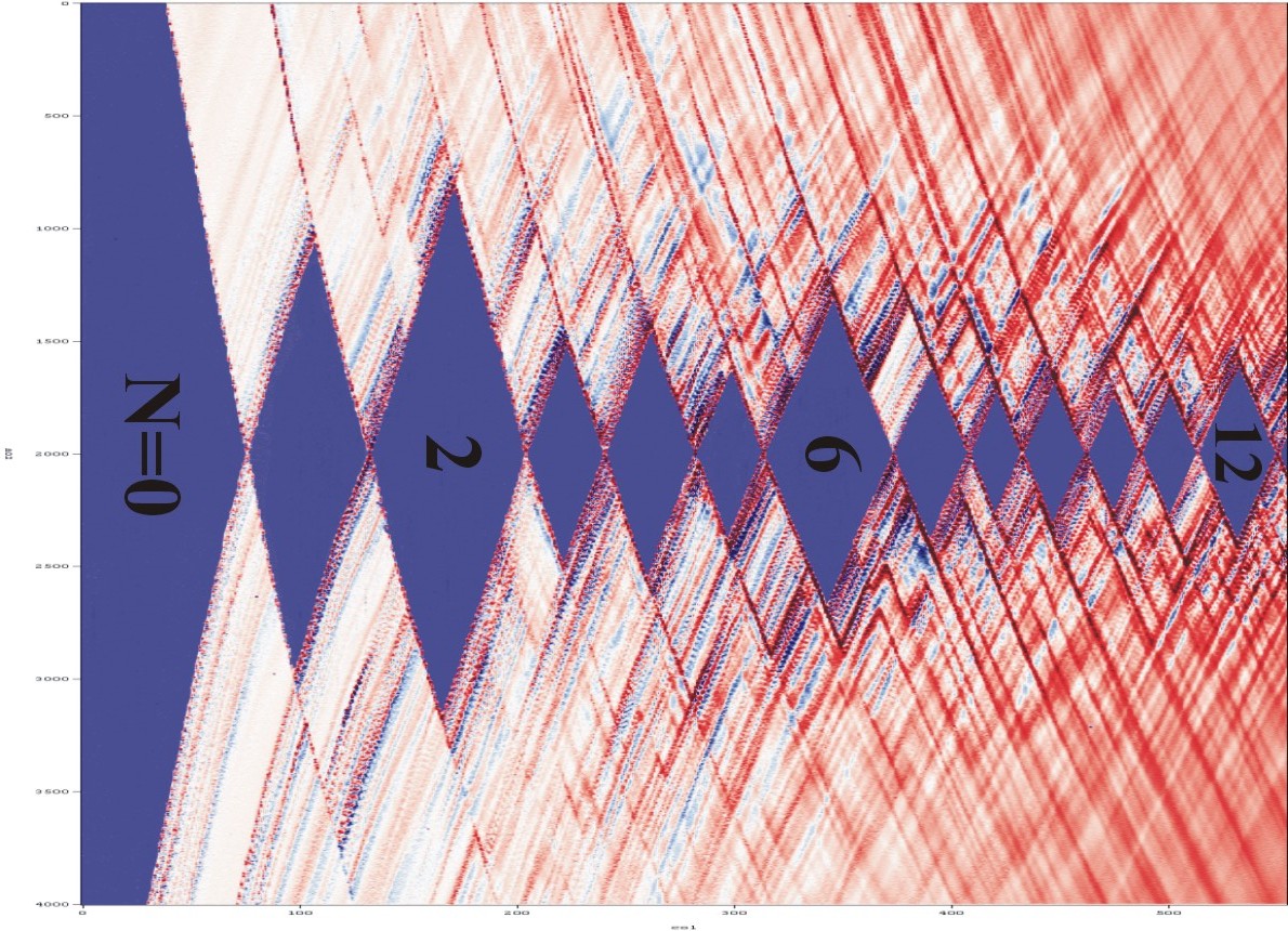
 The picture on the left shows a stability
plot simulated with SIMON. It shows the dI/dV2, where 2*V2
is the bias voltage and I the current through the SET.
Different sized diamonds and lines running parallel to diamond
edges are clearly visible. You can qualitatively compare this
plot to the measurement published in the article "Excitation
Spectra of Circular, Few-Electron Quantum Dots" by Kouwenhoven
et al. in Science, Vol 278, December 1997. The image is reproduced
with permission below. Qualitatively the simulation produces the
same result. The particular energy levels were not known to me
so I couldn't simulate the exact same device.
The picture on the left shows a stability
plot simulated with SIMON. It shows the dI/dV2, where 2*V2
is the bias voltage and I the current through the SET.
Different sized diamonds and lines running parallel to diamond
edges are clearly visible. You can qualitatively compare this
plot to the measurement published in the article "Excitation
Spectra of Circular, Few-Electron Quantum Dots" by Kouwenhoven
et al. in Science, Vol 278, December 1997. The image is reproduced
with permission below. Qualitatively the simulation produces the
same result. The particular energy levels were not known to me
so I couldn't simulate the exact same device.
 This circuit was originally an idea of Paul McEuen and David Dixon
and was later published by Heij,
Dixon, Hadley, and Mooij . This circuit works in the following
way. The SET and the SE-Box have a certain threshold voltage.
For the SET it is the threshold to conduct a current I. For the
SE-Box it is the threshold to admit one more electron into the
box. If the threshold of the SET is lower than the threshold of
the SE-Box the circuit may exhibit a NDR in the following way.
Assume the bias voltage Vb is slowly raised from zero.
At first SET and SE-Box are in Coulomb blockade. At a certain
point the SET will start to conduct current which increases with
increasing bias voltage. When the bias voltage reaches the threshold
of the SE-Box an electron will tunnel onto the central island
of the box. The coupling capacitance Cm makes sure
that the SET is influenced by the electron entering the box. This
influence can be in such a manner, that the SET is put back into
Coulomb blockade. This means that the current will decrease or
even go back to zero, resulting in a negative-differential-resistance.
Increasing the bias voltage Vb even more will finally
make the SET conduct current despite electrons entering or exiting
the box. Thresholds of SET and SE-Box can be tuned by Vg1
and Vg2 respectively. This device was built, measured,
and simulated by the same authors Heij et. al. The measured stability
plot is reproduced here with their permission.Black regions show
NDR onset. A very similar stability plot can be simulated with
SIMON. The simulation shows very good agreement with the measurement.
This circuit was originally an idea of Paul McEuen and David Dixon
and was later published by Heij,
Dixon, Hadley, and Mooij . This circuit works in the following
way. The SET and the SE-Box have a certain threshold voltage.
For the SET it is the threshold to conduct a current I. For the
SE-Box it is the threshold to admit one more electron into the
box. If the threshold of the SET is lower than the threshold of
the SE-Box the circuit may exhibit a NDR in the following way.
Assume the bias voltage Vb is slowly raised from zero.
At first SET and SE-Box are in Coulomb blockade. At a certain
point the SET will start to conduct current which increases with
increasing bias voltage. When the bias voltage reaches the threshold
of the SE-Box an electron will tunnel onto the central island
of the box. The coupling capacitance Cm makes sure
that the SET is influenced by the electron entering the box. This
influence can be in such a manner, that the SET is put back into
Coulomb blockade. This means that the current will decrease or
even go back to zero, resulting in a negative-differential-resistance.
Increasing the bias voltage Vb even more will finally
make the SET conduct current despite electrons entering or exiting
the box. Thresholds of SET and SE-Box can be tuned by Vg1
and Vg2 respectively. This device was built, measured,
and simulated by the same authors Heij et. al. The measured stability
plot is reproduced here with their permission.Black regions show
NDR onset. A very similar stability plot can be simulated with
SIMON. The simulation shows very good agreement with the measurement.

A single-electron pump consisting of three tunnel junctions
and the characteristic 'bee hive' stability plots are shown for
three different temperatures 0K, 30K and 100K.

The theory behind this plot can be found in "Introduction
to Superconductivity" by Tinkham.