Created: 08/19/2024
Updated: 10/11/2024
miniTesla: A new and better way to prototype and build electronics
I became interested in electronics in my early teens. At 14 years of age, I made my first big career decision and decided to enter a technical high school to study electronics. This type of school is unique to Austria, a so-called HTL (Higher Technical Learning Institute), where one has school the entire day, including Saturday, and one does not graduate after 4 years as in a regular high school, but only after 5 years. The advantage of that school type is that one graduates with an engineering degree. It was the hardest school I went to, but also the one I learned most including a lot of hands-on instructions.Since those days of studying electronics, I have thought about ways to prototype and build electronics. The primary reason for this was that back then in the early 1980s, it was very difficult and expensive to make PCBs (printed circuit boards). One could draw with an acid-resistant marker directly on a blank piece of circuit board, put it in an acid (ferric chloride), and then drill and solder the board. But hand drawing is a very crude way to make a PCB and essentially impossible for finer pitch components such as ICs (integrated circuits). To improve the quality of the drawing, one could use acid-resistant tapes and decals but those were too expensive for me. The best way I found was to use perfboard and then solder a wire for each connection. But soldering a circuit made it time-consuming to make changes and thus wasn't a good method to prototype and develop a circuit. I wanted a solderless electronic prototyping system where I could quickly change the circuit. Back then I was not familiar with breadboards. I came up with my first system using so-called "Lötnägel". These were a type of pin that could be soldered into a PCB. It had a female counterpart that could be slipped over the pin creating an electric connection. By soldering components such as resistors and capacitors to these female pin sleeves, and creating arrays of preconnected pins on a PCB, I could connect electronic components without soldering. However, these pins and sleeves were not a good solution because to ensure a good electric connection they had to be tight which made it difficult to connect and disconnect them. Despite its shortcomings, it was my first attempt to design a solderless electronic prototyping system.
Only in the last class of high school, when I was 19 years old, did I for the first time use a breadboard. Breadboards were expensive back then. They worked ok for smaller circuits particularly if an IC was involved, but for larger circuits, they quickly deteriorated into rats-nests of incomprehensible wire connections. Debugging and comprehending circuits on a breadboard was too time-consuming. I was looking for a better way.
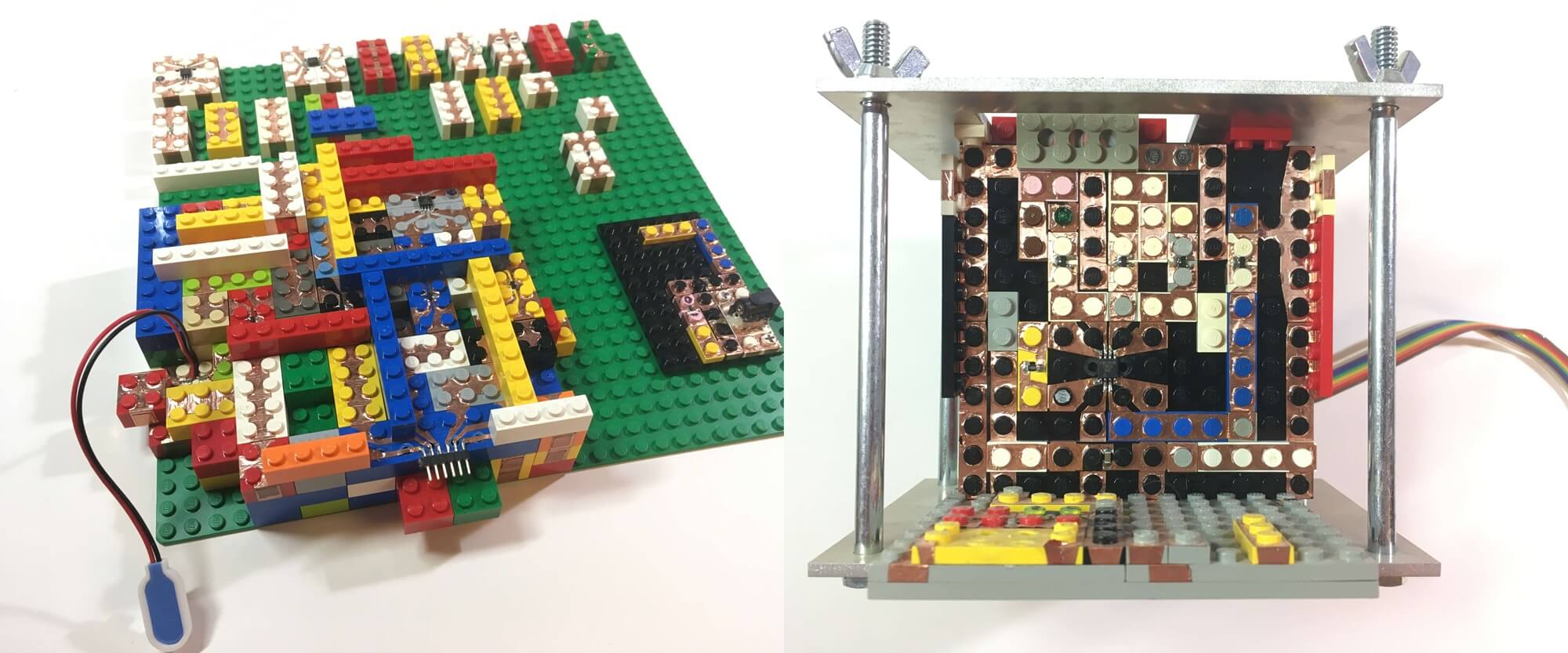
Fast forward several years, after studying electronics at University, and working for Texas Instruments in their R&D department, I decided to go back to school and entered an MBA program at MIT (Sloan). During those two years at MIT, I attended the class "How to Build Almost Anything" (MAS 863) taught by Prof. Neil Gershenfeld at the Media Lab. During that class, I had a new idea of how to prototype electronics. I used Lego pieces and enhanced them with self-adhesive copper tape to enable them to make electric connections. This allowed me to route wires in three dimensions. Components were mounted to Lego parts. This system was quite capable. I built the control electronics for stepper motors that actuated a small CNC mill or plotter. The system had some technical issues but its biggest problem was that it was costly to 'electrify' Lego pieces. I saw no viable way to take this out of the prototype stage.

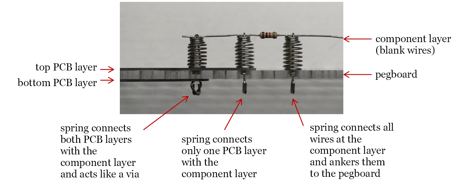
Fast forward another couple of years. I started to tinker a lot more with electronics. I also got more and more frustrated with breadboards. I was not happy developing and building circuits using them. Not only was it cumbersome to develop and prototype with them but in the end one still had to make a PCB because breadboards were not a permanent solution for a circuit, not even a semi-permanent one. As I was mulling over this situation of breadboards I remembered an electronic construction system from my childhood made by Philips. This was several years before I decided to make electronics my profession. I was about 9 or 10 years old when I played with this Philips electronics kit. It used a unique spring contact that firmly held on to wires and component leads. It was entirely solderless, but the spring contact together with a pegboard on which the circuit was built, held everything together such that these circuits could be used long-term. Remembering this system I realized that one could dramatically improve the system by adding small PCBs because the spring contact could connect to these circuit boards at the bottom where it attaches to the pegboard. This would triple the number of connection layers that could be used in this system. The original system could only make connections at the top of the spring contact by clamping to wires. My new idea would add two connection layers, one immediately below the pegboard and a second one immediately above the pegboard. I was ready to switch my prototyping from breadboards to this old Philips system, but it was entirely abandoned. There were no kits and no components available to purchase. I decided to revive this system in a new and improved incarnation. miniTesla was born.

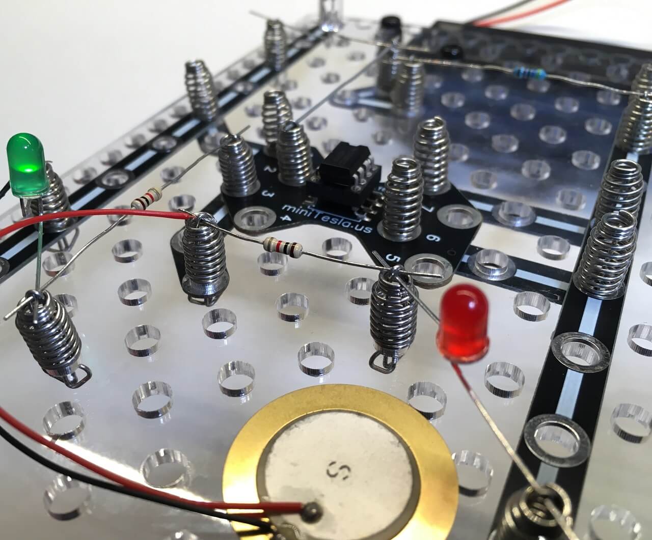
One of the main problems of breadboards is that they only have two connection layers, one built-in (the connected rows), and the other immediately above the breadboard. All other connections have to be routed free-style through the air from one point to another. This makes it very hard to build neat circuits, and it makes it even harder to debug and understand a circuit built on a breadboard. miniTesla offers three connection layers that are not pre-defined and can therefore be used any way one wants to. Essentially, miniTesla can be used like a modular two-layer PCB. The PCB traces either placed immediately below or above the pegboard mimic the top and bottom copper layer of a PCB. Spring contacts can be vias, connecting these two layers, and/or be used as mounting points for components. A circuit can be laid out as drawn in the circuit diagram making testing and understanding a circuit much simpler.

Another problem with breadboards is that the contact springs are very weak which can easily lead to bad connections which are very hard to find and debug. I have spent hours chasing a problem only to find that a bad contact of a breadboard was the fault. Since the contact points are buried inside the breadboard they can't be visually inspected. miniTesla fundamentally improves the situation. The miniTesla spring contacts exert a much higher force and thus create much more reliable connections. It also means that a miniTesla circuit is mechanically much sturdier than one built on a breadboard. A miniTesla circuit can be mounted upside down and can be exposed to shaking and rattling without any connections coming loose. Each spring connection is out in the open and available to be visually inspected. All of this means that a circuit built with miniTesla will function much more reliably than one built on a breadboard.
For the next two years, I developed and tested this system. I eventually realized that switching from a 15 mm raster, which was the original size Philips used, to 16 mm made the system compatible with Lego. This was a very interesting improvement because one could now create all kinds of mechanical add-ons tapping into the vast possibilities Lego and its thousands of components provide. I could build switches, front panels, enclosures, and other electro-mechanical components combining miniTesla and Lego.
Another tweak I made was to add holes in the pegboard at the center of the 16 mm square raster. This shortened the distance to the nearest neighbor spring contact so that one could now use unmodified discrete transistors. The Philips system required each transistor to be mounted to a PCB. With miniTesla, this is unnecessary in the case of transistors and other components that have short leads.
I have completely switched my electronic prototyping, be it for private or professional projects, away from breadboarding to miniTesla. I am so happy that I have finally the system I always wanted. One can build much cleaner with miniTesla. It is easy to probe any point in the circuit with a multimeter or an oscilloscope. If I want to, I can use the miniTesla circuit long-term in a project or keep it as a reference circuit (very practical for teaching purposes). And if I don't want to keep it I can quickly disassemble it into its parts and then use these parts for the next project. It is a flexible system for projects of any size that can be expanded into countless directions.
I am working on a number of bigger projects and builds that combine miniTesla with Lego including an analog synthesizer and drum machine, a remote-controlled car, and a radio. Many more ideas are in the conceptual phase.
Where can one buy miniTesla?
The experienced DIYer who only wants the essential components only needs a bag of the necessary spring contacts. The rest you can do yourself. Make your own pegboard with a laser cutter, CNC mill/router, or careful hand drilling. Add various discrete electronic components (resistors, capacitors, inductors, diodes, LEDs, transistors, ...) and construct a circuit. You may want to add some components that are already mounted to a PCB such as an 8-DIP socket or perhaps an RPi GPIO expansion board if you are working with Raspberry Pi.For those who want a complete kit that includes all the tools and components for your first circuits I highly recommend getting a miniTesla Starter Kit. It includes a printed manual with 47 circuits/experiments. You only need to supply a 9V battery.