This is the Starter Kit for the miniTesla solderless electronic building system. It has over 100 components and a printed instruction booklet with 47 experiments. It includes all the necessary tools and components to complete each circuit. You only need to supply a 9V battery.
In this Starter Kit, we teach electronics by circuit examples rather than the traditional math-heavy approach. In fact, there is no math in the instruction book. We immediately start with small but interesting circuits and short explanations of how they work. This encourages experimentation and emphasizes a playful and experimental approach to electronics. It is more important to see how various components (ex. motor, loudspeaker, LEDs) are used and controlled and how a circuit can sense the environment, amplify signals, and do other cool stuff than to be able to mathematically dimension every component and calculate currents and voltages precisely. Once interest in electronics has been stimulated through interesting applications, the more formal and mathematical side of electronics can be introduced.
A total of 47 experiments are taught. All of these are enabled by three small integrated circuits, an operational amplifier (LM358), the classic 555 timer chip, and an amplifier IC (LM386). These are enhanced by discrete transistors, and a range of passive components. For each experiment, we include a description of what the circuit does and how it does it, the circuit diagram, and a detailed construction drawing of how the circuit can be built in the miniTesla system.
The circuits have been chosen by Burkhard Kainka who has decades of experience creating and designing electronic kits and circuits for Franzis, Kosmos, and Modul-Bus.
Components:
The more than 100 components can be grouped into four categories:
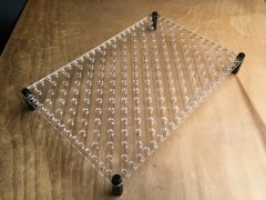
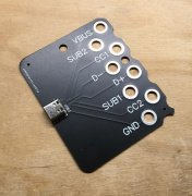
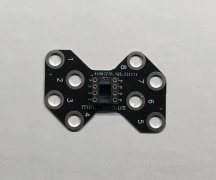
- miniTesla specific: pegboard, spring contacts, and PCBs are specifically made for the miniTesla system. Two of the PCBs have components on them, the socket for the ICs and the other with a potentiometer. The rest of the PCBs are simple traces that connect one point with another. Using PCB traces allows for particularly neat and clear builds but they are not essential. Every connection could be done with a wire clamped into the top of spring contacts. The instruction book is wire bound so that it lays flat with any page open.
- electronic: resistors (2× 100 Ohm, 2× 470 Ohm, 2× 1kOhm, 4.7kOhm, 3× 10kOhm, 22kOhm, 47kOhm, 2× 100kOhm, 220kOhm, 2× 330kOhm, 2× 1MOhm, 2× 2.2MOhm), capacitors (2.2nF, 2× 10nF, 2× 100nF, 1uF, 10uF, 3× 100uF), transistors (2× BC547 NPN, 2× BC557 PNP), three ICs (LM358, NE555, LM386), LEDs (2× red, 2× green, 2× yellow), a phototransistor (PT3346C), diode (1N4148), inductor (470 uH), loudspeaker (8 Ohm), motor, piezo disc, thermistor (NTC 100k Ohm), and 9V battery holder. You can add additional components yourself. One of the advantages of this system is that one can use most electronic components without modification.
- tools: screwdriver, wire cutter, 1.75 mm crochet hook, miniTesla spring compression tool. The screwdriver is primarily used to open and close the 9V battery case. It can also be used for the included hardware. The wire cutter is used to cut pieces from the blank wire as well as for the occasional trimming of component leads. The crochet hook will be a surprise for most. It is an extraction tool to remove spring contacts from the pegboard. One can also pull out these spring contacts by hand. But this hook is convenient for some situations. The spring compression tool is also merely a convenient tool to make inserting wires at the top of the spring contact in some situations easier.
- hardware: some screws and standoffs to make feet for the pegboard as well as to build push buttons from PCB traces.
Contents of the instruction booklet:
- The miniTesla System
- Components
- Resistors and Capacitors
- Potentiometer
- IC Socket
- 1. Operational Amplifier
- 1.1 First Test
- 1.2 Touch Sensor
- 1.3 Run-on Control
- 1.4 Flashlight
- 1.5 Adjustable Flash Length
- 1.6 Light Sensor
- 1.7 Time Delay
- 1.8 Push-Pull Light Sensor
- 1.9 Brightness Comparison
- 1.10 Twilight Switch
- 1.11 Temperature Sensor
- 1.12 Temperature Comparison
- 1.13 LED Blinker
- 1.14 A Soft Blinker
- 1.15 Relaxation Light
- 1.16 Light-Controlled Flashes
- 1.17 Lie Detector
- 2. Timer NE555
- 2.1 On/Off by Touch
- 2.2 Random Switch
- 2.3 Touch Alarm
- 2.4 Light Sensor
- 2.5 Square Wave Generator
- 2.6 Alternating Flasher
- 2.7 Tone Generator
- 2.8 Acoustic Lamp Tester
- 2.9 Temperature Warning Device
- 2.10 Temperature Barrier
- 2.11 Bagpipes
- 2.12 Light Theremin
- 2.13 Temperature-Dependent Siren
- 2.14 Pulse Switch 0,5 s
- 2.15 Timer Switch 10 s
- 2.16 Touch Sensor
- 2.17 Electrostatic Motion Detector
- 2.18 Finger Organ
- 2.19 Passive Infrared Detector
- 3. The LM386 Audio Amplifier
- 3.1 Amplifier
- 3.2 A Tone Generator
- 3.3 The Improved Amplifier
- 3.4 Volume Control
- 3.5 Broadband Spark Receiver
- 3.6 Push-Pull Blinker
- 3.7 Push-Pull Flashing Light
- 3.8 A Ramp Flashing Light
- 3.9 Energy-Saving Light
- 3.10 Motor Control with Touch Sensors
- 3.11 Light-Controlled Motor
- What Happens Next?